Through the efforts of the ATM Forum (jointly founded in 1991 by Cisco Systems, NET/ADAPTIVE, Northern Telecom, and Sprint), ATM is capable of transferring voice, video, and data through private networks and across public networks. ATM continues to evolve today as the various standards groups finalize specifications that allow interoperability among the equipment produced by vendors in the public and private networking industries.
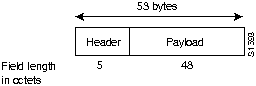
ATM uses very large-scale integration (VLSI) technology to segment data (for example, frames from the data link layer of the OSI reference model) at high speeds into units called cells. Each cell consists of 5 octets of header information and 48 octets of payload data, as shown in Figure 15a-1.
Figure 15a-1 : ATM Cell Format
Cells transit ATM networks by passing through devices known as ATM switches, which analyze information in the header to switch the cell to the output interface that connects the switch to the next appropriate switch as the cell works its way to its destination.
ATM is a cell-switching and multiplexing technology that combines the benefits of circuit switching (constant transmission delay and guaranteed capacity) with those of packet switching (flexibility and efficiency for intermittent traffic). Like X.25 and Frame Relay, ATM defines the interface between the user equipment (such was workstations and routers) and the network (referred to as the User-Network Interface, or UNI). This definition supports the use of ATM switches (and ATM switching techniques) within both public and private networks.
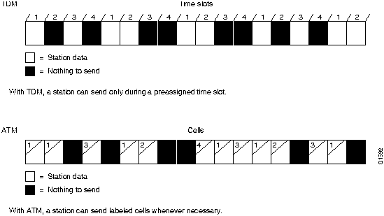
Because it is an asynchronous mechanism, ATM differs from synchronous transfer mode methods, where time-division multiplexing (TDM) techniques are employed to preassign users to time slots. ATM time slots are made available on demand, with information identifying the source of the transmission contained in the header of each ATM cell. TDM is inefficient relative to ATM because if a station has nothing to transmit when its time slot comes up, that time slot is wasted. The converse situation, where one station has lots of information to transmit, is also less efficient. In this case, that station can only transmit when its turn comes up, even though all the other time slots are empty. With ATM, a station can send cells whenever necessary. Figure 15a-2 contrasts TDM and ATM multiplexing techniques.
Figure 15a-2 : TDM and ATM Multiplexing Techniques
Another critical ATM design characteristic is its star topology. The ATM switch acts as a hub in the ATM network, with all devices attached directly. This provides all the traditional benefits of star-topology networks, including easier troubleshooting and support for network configuration changes and additions.
Furthermore, ATM's switching fabric provides additive bandwidth. As long as the switch can handle the aggregate cell transfer rate, additional connections to the switch can be made. The total bandwidth of the system increases accordingly. If a switch can pass cells among all its interfaces at the full rate of all interfaces, it is described as nonblocking. For example, an ATM switch with 16 ports each at 155 megabits per second (Mbps) would require about 2.5 gigabits per second (Gbps) aggregate throughput to be nonblocking.
The ATM standards groups have defined two header formats. The UNI header format is defined by the UNI specification, and the Network-Node Interface (NNI) header format is defined by the NNI specification.
The UNI specification defines communications between ATM endstations (such as workstations and routers) and ATM switches in private ATM networks. The format of the UNI cell header is shown in Figure 15a-3.
Figure 15a-3 : UNI Header Format
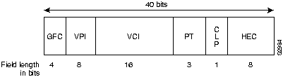
The UNI header consists of the following fields:
- GFC---4 bits of generic flow control that can be used to provide local functions, such as identifying multiple stations that share a single ATM interface. The GFC field is typically not used and is set to a default value.
- VPI---8 bits of virtual path identifier, which is used, in conjunction with the VCI, to identify the next destination of a cell as it passes through a series of ATM switches on its way to its destination.
- VCI---16 bits of virtual channel identifier, which is used, in conjunction with the VPI, to identify the next destination of a cell as it passes through a series of ATM switches on its way to its destination. For more information about how the VPI and VCI fields are used, see the section "ATM Switching," later in this chapter
- PT---3 bits of payload type. The first bit indicates whether the cell contains user data or control data. If the cell contains user data, the second bit indicates congestion, and the third bit indicates whether the cell is the last in a series of cells that represent a single AAL5 frame. (For information about AAL5, see the section "AAL5," later in this chapter.)
- CLP---1 bit of congestion loss priority, which indicates whether the cell should be discarded if it encounters extreme congestion as it moves through the network. For more information about how ATM uses this bit, see the section "Quality of Service," later in this chapter.
- HEC---8 bits of header error control, which is a checksum calculated only on the header itself.
The NNI specification defines communications between ATM switches. The format of the NNI header is shown in Figure 15a-4.
Figure 15a-4 : NNI Header Format
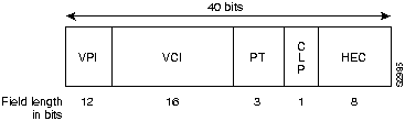
The GFC field is not present in the format of the NNI header. Instead, the VPI field occupies the first 12 bits, which allows ATM switches to assign larger VPI values. With that exception, the format of the NNI header is identical to the format of the UNI header.
Figure 15a-5 is a reference model that illustrates the organization of ATM functionality and the interrelationships between the layers of functionality.
Figure 15a-5 : ATM Reference Model
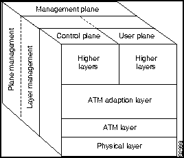
In the ATM reference model, the ATM layer and the ATM adaptation layers are roughly analogous parts of the data link layer of the Open System Interconnection (OSI) reference model, and the ATM physical layer is analogous to the physical layer of the OSI reference model. The control plane is responsible for generating and managing signaling requests. The user plane is responsible for managing the transfer of data. Above the ATM adaptation layer are higher-layer protocols representing traditional transports and applications.
The ATM physical layer controls transmission and receipt of bits on the physical medium. It also keeps track of ATM cell boundaries and packages cells into the appropriate type of frame for the physical medium being used.
The ATM physical layer is divided into two parts: the physical medium sublayer and the transmission convergence sublayer. The physical medium sublayer is responsible for sending and receiving a continuous flow of bits with associated timing information to synchronize transmission and reception. Because it includes only physical-medium-dependent functions, its specification depends on the physical medium used.
ATM can use any physical medium capable of carrying ATM cells. Some existing standards that can carry ATM cells are SONET (Synchronous Optical Network)/SDH, DS-3/E3, 100-Mbps local fiber (Fiber Distributed Data Interface [FDDI] physical layer), and 155-Mbps local fiber (Fiber Channel physical layer). Various proposals for use over twisted-pair wire are also under consideration.
The transmission convergence sublayer is responsible for the following:
- Cell delineation---Maintains ATM cell boundaries.
- Header error control sequence generation and verification---Generates and checks the header error control code to ensure valid data.
- Cell rate decoupling---Inserts or suppresses idle (unassigned) ATM cells to adapt the rate of valid ATM cells to the payload capacity of the transmission system.
- Transmission frame adaptation---Packages ATM cells into frames acceptable to the particular physical-layer implementation.
- Transmission frame generation and recovery---Generates and maintains the appropriate physical-layer frame structure.
The ATM layer is responsible for establishing connections and passing cells through the ATM network. To do this, it uses the information contained in the header of each ATM cell. For more information about how information in the header is used to pass cells through an ATM network, see the section "ATM Switching," later in this chapter.
The ATM adaptation layer (AAL) translates between the larger service data units (SDUs) (for example, video streams, and data packets) of upper-layer processes and ATM cells. Specifically, the ATM adaptation layer (AAL) receives packets from upper-level protocols (such as AppleTalk, Internet Protocols [IP], and NetWare) and breaks them into the 48-byte segments that form the payload field of an ATM cell. Several ATM adaptation layers are currently specified. Table 15a-1 summarizes the characteristics of each AAL.
Table 15a-1 : ATM Adaptation Layers
| Characteristics | AAL1 | AAL3/4 | AAL4 | AAL5 |
|---|---|---|---|---|
| Requires timing between source and destination | Yes | No | No | No |
| Data rate | Constant | Variable | Variable | Variable |
| Connection mode | Connection-oriented | Connection-oriented | Connectionless | Connection-oriented |
| Traffic types | Voice and circuit emulation | Data | Data | Data |
Figure 15a-6 shows how AAL1 prepares a cell for transmission. The payload data consists of a synchronous sample---for example, 1 byte of data generated at a sampling rate of 125 microseconds.
Figure 15a-6 : AAL1 Cell Preparation

The sequence number field (SN) and sequence number protection (SNP) fields provide the information that the receiving AAL1 needs to verify that it has received the cells in the correct order. The remainder of the payload field is filled with enough single bytes to equal 48 bytes.
AAL1 is appropriate for transporting telephone traffic and uncompressed video traffic. It requires timing synchronization between the source and destination and, for that reason, depends on a media that supports clocking, such as SONET. The standards for supporting clock recovery are currently being defined.
AAL3/4 was designed for network service providers and is closely aligned with Switched Multimegabit Data Service (SMDS). AAL3/4 will be used to transmit SMDS packets over an ATM network.
As shown in Figure 15a-7, the convergence sublayer (CS) creates a protocol data unit (PDU) by prepending a Beginning/End Tag header to the frame and appending a length field as a trailer.
Figure 15a-7 : AAL3/4 Cell Preparation
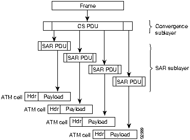
The segmentation and reassembly (SAR) sublayer fragments the PDU and prepends to each PDU fragment a header consisting of the following fields:
- Type---Identifies whether the cell is the beginning of a message, continuation of a message, or end of a message.
- Sequence number---Identifies the order in which cells should be reassembled.
- Multiplexing identifier---Identifies cells from different traffic sources interleaved on the same virtual circuit connection (VCC) so that the correct cells are reassembled at the destination.
The SAR sublayer also appends a CRC-10 trailer to each PDU fragment. The completed SAR PDU becomes the payload field of an ATM cell to which the ATM layer prepends the standard ATM header.
Figure 15a-8 shows how AAL5 prepares a cell for transmission. First, the convergence sublayer of AAL5 appends a variable-length pad and a 8-byte trailer to a frame. The pad is long enough to ensure that the resulting PDU falls on the 48-byte boundary of the ATM cell. The trailer includes the length of the frame and a 32-bit CRC computed across the entire PDU, which allows AAL5 at the destination to detect bit errors and lost or cells that are out of sequence.
Next, the segmentation and reassembly segments the CS PDU into 48-byte blocks. Then the ATM layer places each block into the payload field of an ATM cell. For all cells except the last cell, a bit in the PT field is set to zero to indicate that the cell is not the last cell in a series that represent a single frame. For the last cell, the bit in the PT field is set to one.
Figure 15a-8 : AAL5 Cell Preparation
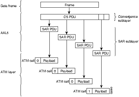
When the cell arrives at its destination, the ATM layer extracts the payload field from the cell; the SAR sublayer reassembles the CS PDU; and the CS uses the CRC and the length field to verify that the frame has been transmitted and reassembled correctly.
AAL5 is the adaptation layer used to transfer most non-SMDS data, such as classical IP over ATM and local-area network (LAN) emulation.
The ATM Forum has adopted the subnetwork model of addressing, in which the ATM layer is responsible for mapping network layer addresses to ATM addresses. Several ATM address formats have been developed---one for public networks and three for private networks. Typically, public ATM networks will use E.164 numbers, which are also used by Narrowband Integrated Services Digital Network (NISDN) networks.
Figure 15a-9 shows the format of private network ATM addresses. The three formats are Data Country Code (DCC), International Code Designator (ICD), and Network Service Access Point (NSAP) encapsulated E.164 addresses.
Figure 15a-9 : ATM Address Formats

The fields of an ATM address are as follows:
AFI---1 byte of authority and format identifier. The AFI field identifies the type of address. The defined values are 45, 47, and 39 for E.164, ICD, and DCC addresses, respectively.
DCC---2 bytes of data country code.
DFI---1 byte of domain specific part (DSP) format identifier.
AA---3 bytes of administrative authority.
RD---2 bytes of routing domain.
Area---2 bytes of area identifier.
ESI---6 bytes of end system identifier, which is an IEEE 802 Media Access Control (MAC) address.
Sel---1 byte of NSAP selector.
ICD---2 bytes of international code designator.
E.164---8 bytes of Integrated Services Digital Network (ISDN) telephone number.
The ATM address formats are modeled on ISO NSAP addresses, but they identify SubNetwork Point of Attachment (SNPA) addresses. Incorporating the MAC address into the ATM address makes it easy to map ATM addresses into existing LANs.
ATM switches use the VPI and VCI fields of the cell header to identify the next network segment that a cell needs to transit on its way to its final destination. A virtual channel is equivalent to a virtual circuit---that is, both terms describe a logical connection between the two ends of a communications connection. A virtual path is a logical grouping of virtual circuits that allows an ATM switch to perform operations on groups of virtual circuits.
The main function of an ATM switch is to receive cells on a port and switch those cells to the proper output port based on the VPI and VCI values of the cell. This switching is dictated by a switching table that maps input ports to output ports based on the values of the VPI and VCI fields, as shown in Figure 15a-10.
Figure 15a-10 : Maintenance of Virtual Connections through an ATM Switch
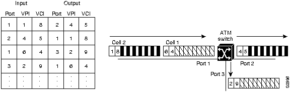
Say, for example, that two cells arrive on port 1 of the ATM switch in Figure 15a-10. First, the switch examines the VPI and VCI fields of cell 1 and finds that the fields have a value of 6 and 4, respectively. The switch examines the switch table to determine on which port it should send the cell. It finds that when it receives a VPI of 6 and a VCI of 4 on port 1, it should send the cell on port 3 with a VPI of 2 and a VCI of 9. So, for cell 1, the switch changes the VPI to 2 and the VCI to 9 and sends the cell out on port 3.
Next, the switch examines cell 2, which has a VPI of 1 and a VCI of 8. The table directs the switch to send out on port 2 cells received on port 1 that have a VPI of 1 and a VCI of 8, respectively, and to change the VPI and VCI to 4 and 5, respectively.
Conversely, when a cell with a VPI and VCI of 2 and 9, respectively, comes in on port 3, the table directs the switch to send the cell out on port 1 with a VPI and VCI of 6 and 4, respectively. When a cell with a VPI and VCI of 4 and 5, respectively, comes in on port 2, the table directs the switch to send the cell out on port 1 with a VPI and VCI of 1 and 8, respectively. Note that VPI and VCI values are significant only to the local interface.
Figure 15a-11 shows how the VPI field is used to group virtual channels (identified by their VCI values) into logical groups. By reducing the number of fields that have to be changed as each cell passes through the switch, the performance of the switch increases.
Figure 15a-11 : Virtual Paths Form Logical Groups of Virtual Channels
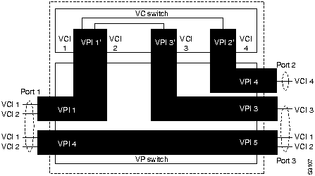
In Figure 15a-11, cells that enter the ATM switch on port 1 and have a VPI value of 4 are processed through the "VP switch," which changes the VPI value of each cell to 5, but leaves the VCI value intact, and sends the cell out on port 3. Cells that have a VPI value of 1 are processed through the "VC switch." For cells that have a VCI value of 1, the VC switch changes the VPI to 4 and the VCI to 4 and sends the cell out on port 2. For cells that have a VCI value of 2, the VC switch changes the VPI to 3 and the VCI to 3 and sends the cell out on port 3.
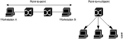
ATM supports two connection types, as shown in Figure 15a-12.
- Point-to-point---Connections of this type can be unidirectional or bidirectional.
- Point-to-multipoint---Connections of this type are unidirectional only.
Figure 15a-12 : ATM Connection Types
It would be desirable for ATM to support mulipoint-to-multipoint links, which would be equivalent to a broadcast VCC. Unfortunately, the AAL5 standard does not provide a way for the receiver to identify individual cells from specific sources when cells are interleaved from multiple sources. This would not allow proper reassembly of cells into frames, unless all of the cells of a specific frame are sent in proper order, without any interleaving.
A multicast server is one solution to this problem. A multicast server can exist in an ATM network, and all members of a multicast group can establish point-to-point VCCs to it. The multicast server would then create a point-to-multipoint VCC to all members on the group, with itself at the root, as shown in Figure 15a-13.
Figure 15a-13 : ATM Multicast Server
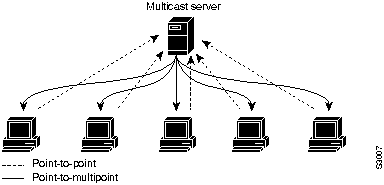
Any data sent to the multicast server is serialized, sent out the point-to-multipoint tree, and received by the members of the group. The value of this approach is that cells from different sources are serialized and sent in order rather than interleaved. The multicast server can also support dynamic groups because members can be added and deleted as leaves on the tree.
ATM permanent virtual connection (PVC) service, shown in Figure 15a-14, operates much like Frame Relay---a virtual connection mesh, partial mesh, or star is administratively established through the ATM network between the routers. ATM PVC service was the original focus of the ATM Forum.
Figure 15a-14 : ATM PVC Service
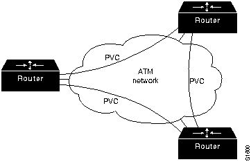
Advantages of ATM PVC service include a direct ATM connection between routers and the simplicity of the specification and subsequent implementation. Disadvantages include static connectivity and the administrative overhead of provisioning virtual connections manually.
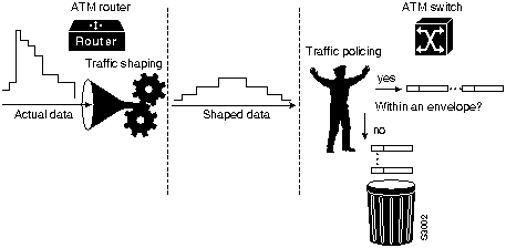
When an ATM endstation connects to the ATM network, it is essentially making a contract with the network based on quality of service (QOS) parameters. This contract specifies an envelope that describes the intended traffic flow. This envelope specifies values for peak bandwidth, average sustained bandwidth, and burst size.
It is the responsibility of the ATM device to adhere to the contract by means of traffic shaping. Traffic shaping is the use of queues to constrain data bursts, limit peak data rate, and smooth jitter so that the traffic will fit within the promised envelope.
ATM switches have the option of using traffic policing to enforce the contract. The switch can measure the actual traffic flow and compare it against the agreed upon traffic envelope. If it finds that traffic is outside of the agreed upon parameters, the switch can set the CLP bit of the offending cells. Setting the CLP bit makes the cell discard eligible, which means that the switch, or any other switch handling the cell, is allowed to drop the cell during periods of congestion, as shown in Figure 15a-15.
Figure 15a-15 : Traffic Shaping and Traffic Policing
Congestion control is a primary concern of ATM designers. For example, dropping just one cell that is part of a FDDI frame can result in the retransmission of 93 cells. Retransmission can lead to an exponential increase in congestion as ATM switches drop individual cells from different packets, resulting in retransmission of more packets, which causes even more cells to be dropped.
The ATM Forum is currently working to define a congestion-control scheme, but that effort is not likely to be completed before mid-1995.
When an ATM device, such as Router A in Figure 15a-16, wants to establish a connection with another ATM device such as Router B, Router A sends a signaling request packet to its directly connected ATM switch. This request contains the ATM address of the desired ATM endpoint (Router B, in this case), as well as any QOS parameters required for the connection.
Figure 15a-16 : Signaling Requests Transit the Network
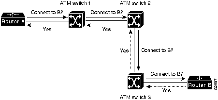
The signaling packet is reassembled by the switch and examined. If the switch has a switch table entry for Router B's ATM address, and it can accommodate the QOS requested for the connection, it sets up the virtual connection on the input link and forwards the request out the interface specified in the switching table for the ATM NSAP of Router B.
Every switch along the path to the endpoint reassembles and examines the signaling packet and forwards it to the next switch if the QOS parameters can be supported while setting up the virtual connection as the signaling packet is forwarded. If any switch along the path cannot accommodate the requested QOS parameters, the request is rejected, and a rejection message is sent back to the originator of the request.
When the signaling packet arrives at the endpoint (Router B), it is reassembled and evaluated. If the endpoint can support the desired QOS, it responds with an accept message. As the accept message propagates back to the originator of the request, the switches set up a virtual circuit. The originator of the request receives the accept message from its directly connected ATM switch, as well as the VPI/VCI value that the originator should use for cells destined for the endpoint.
ATM Forum UNI Specification V3.0 defines the protocols, known as the NNI protocols, used to route ATM signaling requests between switches. The ATM Forum is also working on Private NNI (P-NNI) protocols for use in multiswitch private ATM networks. The ATM Forum has also defined a P-NNI Phase 0 protocol, based on UNI 3.0 signaling and static routes; it is continuing work on a P-NNI Phase 1 protocol that supports dynamic routing.
Главная страница